
 HYDRAULIC COMPONENTS
  HYDRAULIC SYSTEM
  HYDRAULIC SYMBOLS
  HYDRAULIC CALCULATORS
  BUYER’S GUIDES
Hydraulic Hose Size Chart: Complete Guide to Sizes, Standards & Selection
Contents
- 0.1 1. What Is a Hydraulic Hose Size Chart?
- 0.2 1.1 Definition and Purpose
- 0.3 1.2 Key Parameters Included in a Hose Size Chart
- 0.4 1.3 Why Hydraulic Hose Size Charts Matter
- 0.5 1.4 Real-World Use Cases
- 0.6 1.5 Simple Example
- 1 2. Hydraulic Hose Size Basics Explained
- 2 3. Standard Hydraulic Hose Size Chart
- 3 4. Hydraulic Hose Standards and Specifications
- 4 5. How to Read a Hydraulic Hose Size Chart
- 4.1 5.1 Step-by-Step Guide to Reading a Hose Size Chart
- 4.2 5.2 Example: Reading a Hose Size Chart in Practice
- 4.3 5.3 Common Mistakes When Reading Hose Charts
- 4.4 5.4 Pro Tips from Field Experience
- 4.5 5.5 Key Takeaways
- 4.6 6. Flow Rate vs Hose Size
- 4.7 6.1 Relationship Between Flow Rate, Velocity, and Diameter
- 4.8 6.2 Recommended Flow Velocities
- 4.9 6.3 Effects of Incorrect Hose Sizing
- 4.10 6.4 Example Calculation (Practical Case)
- 4.11 6.5 Practical Selection Guidelines
- 4.12 6.6 Key Takeaways
- 4.13 7. Pressure Rating and Hose Size
- 4.14 7.1 What Is Pressure Rating?
- 4.15 7.2 How Hose Size Affects Pressure Rating
- 4.16 7.3 Role of Hose Construction
- 4.17 7.4 Working Pressure vs System Pressure
- 4.18 7.5 Matching Hose Size and Pressure in Real Applications
- 4.19 7.6 Common Mistakes
- 4.20 7.7 Key Takeaways
- 5 8. Hydraulic Hose Bend Radius and Flexibility
- 6 9. Hydraulic Hose Types and Their Sizes
- 6.1 9.1 Braided Hydraulic Hoses
- 6.2 9.2 Spiral Hydraulic Hoses
- 6.3 9.3 Thermoplastic Hydraulic Hoses
- 6.4 9.4 PTFE (Teflon) Hydraulic Hoses
- 6.5 9.5 Rubber Hydraulic Hoses (General Purpose)
- 6.6 9.6 Comparison of Hose Types and Sizes
- 6.7 9.7 Key Takeaways
- 6.8 10. Choosing the Right Hydraulic Hose Size
- 6.9 10.1 Key Factors to Consider
- 6.10 10.2 Application-Based Hose Selection
- 6.11 10.3 Hose Routing and Installation Considerations
- 6.12 10.4 Matching Hose Size with Fittings
- 6.13 10.5 Practical Selection Example
- 6.14 10.6 Common Selection Mistakes
- 6.15 10.7 Key Takeaways
- 6.16 11. Common Mistakes When Using Hydraulic Hose Size Charts
- 7 12. Hydraulic Hose Size Conversion
- 8 13. Applications of Hydraulic Hose Size Charts
- 8.1 14. Maintenance and Inspection of Hydraulic Hoses
- 8.2 14.1 Why Maintenance Matters
- 8.3 14.2 Visual Inspection Checklist
- 8.4 14.3 Measuring Hose Condition in the Field
- 8.5 14.4 Replacement Guidelines
- 8.6 14.5 Preventive Maintenance Best Practices
- 8.7 14.6 Maintenance Schedule (Recommended)
- 8.8 14.7 Key Takeaways
- 9 Conclusion
Hydraulic hoses are a critical component in any fluid power system, serving as the flexible connection that transfers pressurized fluid between pumps, valves, cylinders, and other hydraulic equipment. From heavy-duty excavators and offshore drilling platforms to precision manufacturing machines, hydraulic hoses enable power transmission in environments where rigid piping would be impractical. However, the performance, efficiency, and safety of these systems depend heavily on one key factor: proper hose sizing.
Selecting the correct hose size is not just a matter of fit—it directly impacts flow rate, pressure drop, system responsiveness, and overall reliability. A hose that is too small can restrict flow, causing excessive pressure loss, heat buildup, and potential system failure. On the other hand, an oversized hose may increase costs, reduce efficiency, and complicate installation. This is why engineers and technicians rely on hydraulic hose size charts to ensure optimal selection based on standardized dimensions and performance requirements.
One of the most common sources of confusion in hydraulic systems is the relationship between dash size, inner diameter (ID), and outer diameter (OD). Many assume these values are interchangeable, but in reality, each serves a different purpose. Dash size is a standardized way of expressing hose diameter (typically in increments of 1/16 inch), while ID determines flow capacity, and OD affects routing, space constraints, and compatibility with clamps and fittings. Misunderstanding these distinctions can lead to improper hose selection and costly operational issues.
Hydraulic hose size charts provide a clear and standardized reference for these dimensions, helping professionals quickly identify the correct hose for a given application. These charts typically include key data such as inner diameter, outer diameter, dash size, bend radius, and pressure ratings. By using these charts, engineers can design systems that balance performance, safety, and cost-effectiveness.
Hydraulic hose sizing plays a vital role across multiple industries, including oil and gas, construction, agriculture, manufacturing, and aerospace. Whether it’s ensuring consistent flow in a high-pressure drilling operation or maintaining precision in an automated production line, the right hose size can make the difference between smooth operation and system failure.
In this guide, we will break down everything you need to know about hydraulic hose size charts—from understanding basic sizing concepts to reading charts, selecting the right hose, and avoiding common mistakes. By the end, you’ll have a clear, practical understanding of how to choose the right hydraulic hose size for any application.
1. What Is a Hydraulic Hose Size Chart?

A hydraulic hose size chart is a standardized reference tool used to identify and compare the physical dimensions and key performance parameters of hydraulic hoses. It allows engineers, technicians, and system designers to quickly select the correct hose size based on application requirements such as flow rate, pressure, and installation constraints.
1.1 Definition and Purpose
At its core, a hydraulic hose size chart provides a structured table that lists hose sizes alongside their corresponding dimensions and specifications. These charts are designed to simplify the selection process by translating complex engineering data into an easy-to-read format.
The main purposes of a hydraulic hose size chart include:
- Standardizing hose dimensions across manufacturers
- Helping users match hoses with compatible fittings and components
- Ensuring proper flow and pressure performance
- Reducing the risk of system failure due to incorrect sizing
In industries like oil & gas, construction, and manufacturing, where hydraulic systems operate under high pressure, using the correct hose size is essential for both safety and efficiency.
1.2 Key Parameters Included in a Hose Size Chart
A typical hydraulic hose size chart includes several important parameters:
- Dash Size
A standardized number representing the hose’s inner diameter in increments of 1/16 inch (e.g., -8 = 1/2 inch). - Inner Diameter (ID)
The most critical dimension, as it determines how much fluid can flow through the hose. - Outer Diameter (OD)
The total outside measurement of the hose, important for routing, clamps, and space constraints. - Working Pressure
The maximum pressure the hose can safely handle during operation. - Burst Pressure
The pressure at which the hose will fail, typically 4 times the working pressure. - Minimum Bend Radius
The smallest radius the hose can bend without damage. - Weight
Useful for installation planning and system load considerations.
1.3 Why Hydraulic Hose Size Charts Matter
Hydraulic systems rely on precise fluid flow and pressure control. A hose size chart helps ensure that:
- Flow velocity stays within recommended limits
- Pressure drop is minimized
- Heat generation is controlled
- System components operate efficiently
Without a proper size chart, selecting hoses becomes guesswork—leading to issues such as energy loss, overheating, and premature hose failure.
1.4 Real-World Use Cases
Hydraulic hose size charts are used in both design and field applications:
- System Design Phase
Engineers use charts to size hoses based on flow calculations and pressure requirements. - Maintenance and Replacement
Technicians reference charts to identify correct replacement hoses for existing systems. - Troubleshooting
Charts help diagnose issues like excessive pressure drop or overheating caused by undersized hoses.
1.5 Simple Example
For example, if a system requires a flow rate that corresponds to a -8 hose (1/2 inch ID), the chart will confirm:
- Inner diameter = 0.5 inch
- Suitable pressure rating
- Required bend radius
- Compatible fittings
This ensures the hose will perform correctly without compromising safety or efficiency.
2. Hydraulic Hose Size Basics Explained
Understanding hydraulic hose sizing starts with a few fundamental concepts. While hose charts provide the data, you need to understand what each parameter actually means and how it affects system performance. The most important elements are inner diameter (ID), outer diameter (OD), and dash size, along with the distinction between nominal and actual measurements.
2.1 Inner Diameter (ID)

The inner diameter (ID) is the most critical dimension in any hydraulic hose. It represents the internal opening through which fluid flows.
Why ID matters:
- Determines flow capacity
- Directly affects fluid velocity
- Influences pressure drop across the system
A larger ID allows more fluid to pass through with lower resistance, reducing energy loss. A smaller ID, on the other hand, increases velocity and friction, which can lead to:
- Excess heat generation
- Increased pressure loss
- Reduced system efficiency

👉 In hydraulic design, selecting the correct ID ensures that flow remains within recommended velocity limits.
2.2 Outer Diameter (OD)

The outer diameter (OD) is the total outside measurement of the hose, including reinforcement layers and outer cover.
Why OD matters:
- Determines installation space requirements
- Affects clamp and bracket sizing
- Impacts routing in tight spaces
Unlike ID, OD does not directly affect flow, but it is crucial for mechanical fit and durability. Two hoses with the same ID can have different ODs depending on:
- Reinforcement type (braided vs spiral)
- Pressure rating
- Material construction
👉 Always check OD when designing hose routing layouts or selecting mounting hardware.
2.3 Dash Size System

The dash size system is a standardized way of expressing hose size, widely used in the hydraulic industry.
How it works:
- Dash size represents the hose ID in 1/16 inch increments
- Written as a dash followed by a number (e.g., -4, -8, -16)
Examples:
- -4 → 4/16 inch = 1/4 inch ID
- -8 → 8/16 inch = 1/2 inch ID
- -16 → 16/16 inch = 1 inch ID
Why dash size is useful:
- Provides a quick shorthand for hose sizing
- Ensures compatibility with fittings
- Standard across most hydraulic systems
👉 When selecting fittings, the dash size of the hose and fitting must match exactly.
2.4 Nominal vs Actual Size

Hydraulic hoses are typically specified using nominal sizes, but the actual dimensions may vary slightly.
Key differences:
- Nominal size: Standardized reference value (e.g., 1/2 inch)
- Actual size: Real measured dimension (may differ slightly)
Why this happens:
- Manufacturing tolerances
- Material expansion or contraction
- Reinforcement layer variations
Why it matters:
- Slight differences can affect fitting compatibility
- Important for precision systems (e.g., semiconductor or high-purity applications)
👉 Always refer to manufacturer specifications when tight tolerances are required.
2.5 Key Takeaways
- ID controls flow and pressure performance → most critical parameter
- OD affects installation and routing → mechanical consideration
- Dash size simplifies selection → industry standard
- Nominal ≠ exact measurement → always verify specs
By mastering these basics, you’ll be able to read hydraulic hose size charts accurately and make better decisions when selecting hoses for real-world applications.
3. Standard Hydraulic Hose Size Chart
A standard hydraulic hose size chart provides a quick reference for selecting the correct hose based on dash size, inner diameter (ID), outer diameter (OD), and typical applications. These charts are widely used in design, maintenance, and procurement to ensure compatibility and performance.
3.1 Hydraulic Hose Size Chart (Inch)

Below is a standard inch-based hydraulic hose size chart (commonly used in the US and global oil & gas industry):
| Dash Size | ID (inch) | ID (mm) | Typical OD (mm) | Common Applications |
|---|---|---|---|---|
| -2 | 1/8 | 3.2 | ~8–10 | Instrumentation, pilot lines |
| -3 | 3/16 | 4.8 | ~10–12 | Low-flow hydraulic systems |
| -4 | 1/4 | 6.4 | ~12–14 | Control lines, small equipment |
| -5 | 5/16 | 7.9 | ~14–16 | Specialized applications |
| -6 | 3/8 | 9.5 | ~16–18 | General hydraulics |
| -8 | 1/2 | 12.7 | ~18–22 | Medium flow systems |
| -10 | 5/8 | 15.9 | ~22–26 | Construction equipment |
| -12 | 3/4 | 19.1 | ~26–30 | High-flow return lines |
| -16 | 1 | 25.4 | ~32–38 | Heavy machinery |
| -20 | 1-1/4 | 31.8 | ~40–48 | Large hydraulic systems |
| -24 | 1-1/2 | 38.1 | ~48–55 | Mining, oil & gas |
| -32 | 2 | 50.8 | ~60–70 | Bulk fluid transfer |
👉 Note: Outer diameter (OD) varies depending on hose construction (braided vs spiral).
3.2 Hydraulic Hose Size Chart (Metric)

| ID (mm) | Equivalent Inch | Approx. Dash Size | Typical Use |
|---|---|---|---|
| 3 | 1/8 | -2 | Precision systems |
| 5 | 3/16 | -3 | Instrumentation |
| 6 | 1/4 | -4 | Light hydraulics |
| 8 | 5/16 | -5 | Specialized systems |
| 10 | 3/8 | -6 | General use |
| 12 | 1/2 | -8 | Medium flow |
| 16 | 5/8 | -10 | Equipment hydraulics |
| 20 | 3/4 | -12 | Return lines |
| 25 | 1 | -16 | Heavy-duty systems |
| 32 | 1-1/4 | -20 | Industrial hydraulics |
| 38 | 1-1/2 | -24 | Oil & gas |
| 50 | 2 | -32 | Bulk transfer |
👉 Metric sizes are often rounded, so always verify exact specifications from manufacturers.
3.3 Dash Size Conversion Table


The dash size system is the most commonly used shorthand in hydraulic systems.
| Dash Size | Inch (ID) | mm (ID) |
|---|---|---|
| -2 | 1/8 | 3.2 |
| -4 | 1/4 | 6.4 |
| -6 | 3/8 | 9.5 |
| -8 | 1/2 | 12.7 |
| -10 | 5/8 | 15.9 |
| -12 | 3/4 | 19.1 |
| -16 | 1 | 25.4 |
| -20 | 1-1/4 | 31.8 |
| -24 | 1-1/2 | 38.1 |
| -32 | 2 | 50.8 |
👉 Rule:
Dash size = ID (inch) × 16
3.4 Common Hose Sizes Used in Industry

Different hose sizes are used depending on the application:
Small Sizes (-2 to -6)
- Used in:
- Instrumentation
- Pilot lines
- Precision hydraulic systems
- Characteristics:
- Low flow
- High control accuracy
Medium Sizes (-8 to -16)
- Most common range in industry
- Used in:
- Construction equipment
- Manufacturing systems
- Mobile hydraulics
- Balanced between flow and flexibility
Large Sizes (-20 and above)
- Used in:
- Mining equipment
- Oil & gas systems
- Bulk fluid transfer
- Characteristics:
- High flow capacity
- Lower velocity
- Heavy-duty construction
3.5 Key Takeaways
- Hydraulic hose size charts standardize ID, OD, and dash size
- Dash size is the fastest way to identify hose size
- Metric and inch systems must be carefully converted
- Always consider:
- Application
- Flow rate
- Pressure requirements
This standardized chart is the foundation for selecting the correct hose in any hydraulic system. In the next section, we’ll dive into standards like SAE and ISO that define these hose sizes globally.
4. Hydraulic Hose Standards and Specifications
Hydraulic hoses are not just sized—they are governed by international standards that define their construction, dimensions, pressure ratings, and performance requirements. These standards ensure that hoses from different manufacturers are interchangeable, reliable, and safe in demanding applications such as oil & gas, construction, and industrial systems.
Understanding these standards is essential when selecting hoses, especially for projects involving global suppliers, EPC contractors, or high-risk environments.
4.1 SAE International (SAE J517)

The SAE J517 standard is one of the most widely used hydraulic hose specifications globally, especially in North America and oil & gas industries.
Key Features:
- Defines hose series such as:
- SAE 100R1 (single wire braid)
- SAE 100R2 (double wire braid)
- SAE 100R12 / R13 / R15 (spiral high-pressure hoses)
- Specifies:
- Inner diameter (ID)
- Outer diameter (OD)
- Pressure ratings
- Bend radius
- Uses the dash size system (e.g., -8, -16)
Why SAE J517 matters:
- Ensures compatibility between hoses and fittings
- Widely accepted in US-based and global projects
- Critical for mobile equipment and heavy machinery
👉 In real projects (like refinery or offshore), SAE hoses are often the default unless specified otherwise.
4.2 International Organization for Standardization (ISO 18752)
The ISO 18752 standard takes a different approach—it classifies hoses based on performance rather than construction.
Key Features:
- Uses performance classes instead of hose types
- Defines:
- Pressure classes (e.g., 350 bar, 420 bar)
- Temperature resistance
- Impulse cycle life
- Focuses on real-world durability
Advantages over SAE:
- More flexible design options
- Better suited for modern high-performance systems
- Allows manufacturers to innovate beyond fixed constructions
👉 ISO 18752 is increasingly used in OEM equipment and global industrial systems.
4.3 EN Standards (European Norms)

In Europe, hydraulic hoses are commonly specified under EN (European Norm) standards, such as:
- EN 853 → Braided hoses (similar to SAE 100R1 / R2)
- EN 856 → Spiral hoses (similar to SAE R12 / R13)
Key Differences:
- Often use metric sizing (mm) instead of inch-based dash sizes
- Slight variations in:
- Pressure ratings
- Dimensional tolerances
- Common in:
- European machinery
- Automotive systems
- Industrial manufacturing
👉 When working with European equipment, always verify metric compatibility.
4.4 Other Relevant Standards

Beyond SAE, ISO, and EN, several additional standards may apply:
DIN Standards (Germany)
- Similar to EN standards
- Widely used in European engineering
ISO 1436 / ISO 3862
- Older ISO hose standards
- Still referenced in some projects
MSHA (Mine Safety and Health Administration)
- Required for hoses used in mining environments
- Focus on fire resistance and safety
4.5 Why Standards Matter in Real Projects
Using standardized hydraulic hoses ensures:
1. Interchangeability
- Hoses and fittings from different suppliers can work together
2. Safety Compliance
- Prevents failures under high pressure
- Meets regulatory requirements
3. Performance Reliability
- Ensures hoses can handle:
- Pressure cycles
- Temperature extremes
- Harsh environments
4. Global Project Compatibility
- Critical for EPC projects (refineries, LNG, semiconductor fabs)
- Avoids mismatch between US, EU, and Asian systems
4.6 Practical Insight (From Field Experience)
In real-world projects (like refinery turnarounds or gas systems):
- Mixing SAE and metric hoses can cause serious compatibility issues
- Always verify:
- Hose standard
- Fitting type
- Thread standard (NPT, BSP, etc.)
👉 A mismatch here can lead to:
- Leakage
- Installation delays
- Safety risks
4.7 Key Takeaways
- SAE J517 → Most common, construction-based standard
- ISO 18752 → Performance-based, modern approach
- EN standards → Metric-focused, European systems
- Standards ensure:
- Safety
- Compatibility
- Reliability
Understanding these standards is essential before selecting a hose. In the next section, we’ll go deeper into how to read a hydraulic hose size chart step by step—so you can apply these standards in real applications.
5. How to Read a Hydraulic Hose Size Chart
Reading a hydraulic hose size chart is a practical skill that bridges theory and real-world application. While the chart itself may look like a simple table, selecting the correct hose requires understanding how flow rate, pressure, size, and installation constraints all work together.
5.1 Step-by-Step Guide to Reading a Hose Size Chart
Follow this structured process when using a hydraulic hose size chart:
Step 1: Determine the Required Flow Rate
- Identify the system’s flow rate (e.g., L/min or GPM)
- This is the starting point for selecting hose size
- Higher flow requires larger inner diameter (ID)
👉 Example:
A system with 50 L/min flow typically needs at least a -8 (1/2″) hose
Step 2: Select the Appropriate Inner Diameter (ID)
- Use the chart to match flow rate with hose ID
- Ensure flow velocity stays within recommended limits:
- Pressure lines: ~3–6 m/s
- Return lines: ~2–3 m/s
- Suction lines: ~0.5–1.5 m/s
👉 The ID is the most important parameter in the chart.
Step 3: Check the Pressure Rating
- Verify the hose can handle system pressure
- Compare:
- Working pressure (continuous operation)
- Burst pressure (safety limit)
👉 Rule of thumb:
Burst pressure should be ≥ 4× working pressure
Step 4: Verify Bend Radius
- Check the minimum bend radius from the chart
- Ensure installation does not exceed this limit
👉 Too tight bending leads to:
- Hose kinking
- Internal damage
- Reduced lifespan
Step 5: Confirm Outer Diameter (OD) and Space Constraints
- Use OD to verify:
- Clearance in routing paths
- Compatibility with clamps and brackets
- Important in compact systems or machinery
Step 6: Match Hose with Fittings
- Ensure:
- Same dash size
- Compatible thread type (NPT, BSP, etc.)
- Avoid mixing standards unless verified
5.2 Example: Reading a Hose Size Chart in Practice

Scenario:
- Flow rate: 60 L/min
- System pressure: 210 bar
- Application: Hydraulic cylinder
Step-by-step selection:
- From flow → choose -8 or -10 hose
- Check ID:
- -8 (1/2″) may be borderline
- -10 (5/8″) provides better efficiency
- Verify pressure rating:
- Select hose rated ≥ 210 bar
- Confirm bend radius fits installation
- Match fittings (-10 size)
👉 Final choice: -10 hydraulic hose
5.3 Common Mistakes When Reading Hose Charts
Avoid these frequent errors:
1. Choosing Based Only on OD
- OD does not determine flow
- Always prioritize ID
2. Ignoring Pressure Rating
- Underrated hoses can burst
- Always check working pressure
3. Misinterpreting Dash Size
- Dash size refers to ID, not OD
- Example: -8 = 1/2″ ID
4. Overlooking Bend Radius
- Leads to premature failure
- Especially critical in tight installations
5. Mixing Metric and Inch Systems
- Can cause:
- Fitting mismatch
- Leakage
- Installation issues
5.4 Pro Tips from Field Experience
- Always oversize slightly if flow is borderline → reduces pressure loss
- In high-cycle systems → prioritize flexibility and bend radius
- For critical applications → cross-check:
- Manufacturer datasheets
- Actual OD and tolerances
👉 In refinery or gas projects, incorrect hose selection can delay commissioning and create safety risks.
5.5 Key Takeaways
- Start with flow rate → select ID
- Verify pressure rating and bend radius
- Use OD for installation checks
- Always ensure fitting compatibility
- Avoid mixing standards without verification
6. Flow Rate vs Hose Size
The relationship between flow rate and hydraulic hose size is one of the most important factors in fluid system design. Choosing the correct hose diameter ensures efficient fluid transfer, minimizes energy loss, and prevents overheating or premature system failure.
At the core of this relationship is a simple principle:
👉 For a given flow rate, the hose size determines fluid velocity—and velocity directly affects system performance.
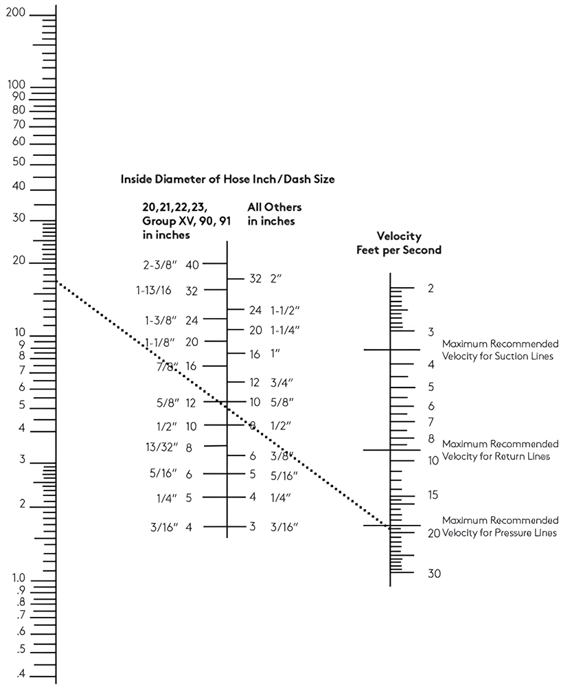
6.1 Relationship Between Flow Rate, Velocity, and Diameter

The flow of fluid through a hose is governed by the relationship:
- Flow Rate (Q) = Velocity (V) × Cross-sectional Area (A)
This means:
- Smaller hose (low ID) → higher velocity → more friction
- Larger hose (high ID) → lower velocity → less resistance
Key Impacts:
- High velocity increases:
- Pressure drop
- Heat generation
- Internal wear
- Low velocity improves:
- Efficiency
- Component lifespan
👉 That’s why selecting the correct hose size is essential—not too small, not unnecessarily large.
6.2 Recommended Flow Velocities

Different parts of a hydraulic system require different flow velocities:
| Line Type | Recommended Velocity |
|---|---|
| Suction lines | 0.5 – 1.5 m/s |
| Return lines | 2 – 3 m/s |
| Pressure lines | 3 – 6 m/s |
Why these limits matter:
- Suction lines: Prevent cavitation and air entrainment
- Pressure lines: Balance efficiency and responsiveness
- Return lines: Avoid excessive backpressure
👉 Exceeding these limits leads to serious performance issues.
6.3 Effects of Incorrect Hose Sizing
If the hose is too small:
- High fluid velocity
- Increased friction and pressure drop
- Heat buildup → oil degradation
- Reduced system efficiency
- Risk of hose failure
If the hose is too large:
- Higher cost and weight
- Slower system response
- Difficult installation in tight spaces
👉 The goal is to find the optimal size that balances performance, cost, and installation.
6.4 Example Calculation (Practical Case)
Given:
- Flow rate: 50 L/min
- Application: Pressure line
Step 1: Convert flow rate
50 L/min ≈ 0.00083 m³/s
Step 2: Choose velocity target
Use ~4 m/s (within 3–6 m/s range)
Step 3: Calculate required area
A = Q / V = 0.00083 / 4 ≈ 0.00021 m²
Step 4: Convert to diameter
D ≈ 16 mm (~5/8 inch)
👉 Result:
A -10 hose (5/8″) is appropriate for this flow rate.
6.5 Practical Selection Guidelines
- Always start with flow rate → determine ID
- Keep velocity within recommended ranges
- Slightly oversize if uncertain to reduce pressure loss
- Consider:
- Fluid type (oil, gas, chemicals)
- Temperature effects
- System duty cycle
6.6 Key Takeaways
- Flow rate and hose size are directly linked through velocity
- Too small = high velocity + heat + pressure loss
- Too large = inefficiency + cost
- Use recommended velocity ranges for each line type
- Proper sizing ensures:
- Efficiency
- Safety
- Long system life
7. Pressure Rating and Hose Size
Selecting the correct hydraulic hose is not only about diameter—it must also safely withstand the system pressure. The relationship between pressure rating and hose size is critical to ensure reliability, prevent failures, and meet safety standards in hydraulic systems.
7.1 What Is Pressure Rating?

The pressure rating of a hydraulic hose defines how much pressure it can safely handle during operation.
Key Terms:
- Working Pressure
The maximum pressure the hose can handle continuously. - Burst Pressure
The pressure at which the hose will fail or rupture. - Safety Factor
Typically 4:1, meaning:- If working pressure = 250 bar
- Burst pressure ≈ 1000 bar
👉 This safety margin protects against pressure spikes and dynamic loads.
7.2 How Hose Size Affects Pressure Rating

Hose size (diameter) directly influences pressure capacity:
General Rule:
- Smaller diameter hoses → higher pressure rating
- Larger diameter hoses → lower pressure rating
Why?
- Larger hoses experience:
- Greater internal force
- More stress on reinforcement layers
- Smaller hoses:
- Have stronger structural integrity relative to size
Example:
- A -6 hose (3/8″) may handle higher pressure than a
- -16 hose (1″) of the same construction type
👉 This is why you must always check pressure ratings—not assume based on size.
7.3 Role of Hose Construction
Pressure rating is heavily influenced by hose construction, not just size.
Common Types:
Braided Hoses (e.g., SAE 100R1, 100R2)
- Steel wire braid reinforcement
- Medium pressure applications
Spiral Hoses (e.g., SAE R12, R13, R15)
- Multiple spiral layers
- Designed for very high pressure
Thermoplastic Hoses
- Lightweight
- Moderate pressure capacity
👉 Two hoses with the same size can have completely different pressure ratings depending on construction.
7.4 Working Pressure vs System Pressure

Hydraulic systems rarely operate at constant pressure. They experience:
- Pressure spikes
- Pulsations
- Dynamic loading
Best Practice:
- Select hose with working pressure ≥ maximum system pressure
- Include margin for:
- Surge pressure
- Shock loads
👉 Never size a hose exactly at system pressure—always allow a safety buffer.
7.5 Matching Hose Size and Pressure in Real Applications
Example Scenario:
- System pressure: 300 bar
- Flow requires: -12 hose (3/4″)
Selection process:
- Identify hose size (-12)
- Check pressure rating:
- Standard braided hose may not be sufficient
- Upgrade to:
- Spiral hose (e.g., SAE R13)
- Verify:
- Working pressure ≥ 300 bar
- Suitable safety factor
👉 Final selection depends on both size AND construction.
7.6 Common Mistakes

Avoid these critical errors:
1. Ignoring Pressure Rating
- Leads to hose rupture
- Major safety hazard
2. Assuming Larger Hose = Stronger
- Larger diameter often means lower pressure capacity

3. Not Considering Pressure Spikes
- Transient pressure can exceed rated limits
4. Mixing Hose Types Incorrectly
- Using low-pressure hose in high-pressure system
7.7 Key Takeaways
- Pressure rating is as important as hose size
- Always check:
- Working pressure
- Burst pressure
- Safety factor (4:1)
- Larger hoses typically have lower pressure ratings
- Hose construction (braided vs spiral) is critical
- Always allow margin for pressure spikes
Choosing the right hydraulic hose means balancing flow requirements (size) with pressure capability (strength). In the next section, we’ll explore how bend radius and flexibility affect hose performance and installation.
8. Hydraulic Hose Bend Radius and Flexibility
The bend radius of a hydraulic hose is a critical parameter that determines how tightly the hose can be curved without causing damage. Along with flexibility, it plays a major role in installation, durability, and long-term system performance. Even if a hose meets the correct size and pressure requirements, improper bending can lead to premature failure.
8.1 What Is Minimum Bend Radius?

The minimum bend radius is the smallest radius a hose can be bent without damaging its internal structure.
Key points:
- Measured from the centerline of the hose curve
- Specified by the manufacturer for each hose type and size
- Typically increases with:
- Larger hose diameters
- Higher pressure ratings
👉 Exceeding the bend radius (bending too tightly) can cause internal damage even if it’s not visible externally.
8.2 Why Bend Radius Matters

Improper bending has serious consequences:
1. Hose Kinking
- Restricts or blocks fluid flow
- Causes pressure spikes
2. Internal Layer Damage
- Breaks reinforcement wires
- Weakens hose structure
3. Reduced Hose Life
- Leads to cracks and fatigue failure
- Accelerates wear under cyclic loading
4. Flow Restriction
- Increases pressure drop
- Reduces system efficiency
👉 Many hydraulic failures are caused not by pressure—but by poor hose routing.
8.3 Relationship Between Hose Size and Flexibility
Flexibility varies depending on hose size and construction:
General trends:
- Smaller hoses → more flexible → tighter bend radius
- Larger hoses → stiffer → larger bend radius
Construction impact:
- Braided hoses → more flexible
- Spiral hoses → stiffer but handle higher pressure
👉 High-pressure hoses (spiral) often require more installation space due to reduced flexibility.
8.4 Best Practices for Hose Routing


Proper routing is essential to maintain bend radius and flexibility:
1. Avoid Sharp Bends
- Always follow manufacturer’s minimum bend radius
2. Use Smooth Curves
- Gradual bends reduce stress and improve flow
3. Prevent Twisting
- Twisting weakens hose structure and reduces life
4. Use Clamps and Supports
- Secure hoses to prevent excessive movement
5. Allow for Movement
- Account for vibration and dynamic motion in machinery
8.5 Bend Radius vs Hose Length
- Short hoses are more likely to be over-bent
- Longer hoses allow smoother routing
- Avoid forcing hoses into tight spaces
👉 If space is limited, consider:
- Using smaller diameter hoses (if flow allows)
- Switching to more flexible hose types
8.6 Real-World Example
Scenario:
- Large hydraulic hose (-16) installed in tight equipment space
Problem:
- Hose bent below minimum radius → internal damage
Solution:
- Re-route with larger bend radius
- Add support clamps
- Replace with correct hose type if needed
👉 Result:
- Improved reliability
- Reduced maintenance issues
8.7 Key Takeaways
- Bend radius defines how tightly a hose can safely bend
- Exceeding limits leads to:
- Kinking
- Internal damage
- Early failure
- Larger hoses = less flexible
- Proper routing is just as important as correct sizing
- Always follow manufacturer specifications
Understanding bend radius and flexibility ensures your hydraulic system is not only efficient—but also durable and safe over time. Up next, we’ll explore different types of hydraulic hoses and their size characteristics.
9. Hydraulic Hose Types and Their Sizes
Hydraulic hoses come in different types and constructions, each designed for specific pressure ranges, flexibility requirements, and environmental conditions. While hose size charts define dimensions like ID and dash size, the type of hose determines how those sizes perform in real applications.
Understanding the relationship between hose type and size helps ensure you select the right combination of diameter, pressure capability, and flexibility.
9.1 Braided Hydraulic Hoses

Braided hoses are among the most commonly used hydraulic hoses, especially in general industrial and mobile equipment.
Construction:
- Inner tube (rubber or synthetic material)
- One or two layers of steel wire braid
- Outer protective cover
Common Standards:
- SAE 100R1 (single braid)
- SAE 100R2 (double braid)
Typical Size Range:
- -4 to -16 (1/4″ to 1″)
- Occasionally up to -20
Key Characteristics:
- Good flexibility
- Moderate pressure rating
- Widely available and cost-effective
Applications:
- Construction equipment
- Industrial machinery
- General hydraulic systems
👉 Best choice for medium-pressure systems with moderate flexibility needs.
9.2 Spiral Hydraulic Hoses
Spiral hoses are designed for high-pressure and heavy-duty applications.
Construction:
- Multiple layers of spiral-wound steel wire
- Thick, robust outer cover

Common Standards:
- SAE 100R12
- SAE 100R13
- SAE 100R15
Typical Size Range:
- -8 to -32 (1/2″ to 2″)
Key Characteristics:
- Very high pressure capacity
- Lower flexibility (stiffer than braided hoses)
- Larger outer diameter
Applications:
- Mining equipment
- Oil & gas systems
- Heavy construction machinery
👉 Ideal for high-pressure systems where durability is critical.
9.3 Thermoplastic Hydraulic Hoses

Thermoplastic hoses are made from synthetic materials instead of rubber, offering unique advantages.
Construction:
- Thermoplastic inner core
- Fiber or synthetic reinforcement
- Outer protective layer
Typical Size Range:
- -2 to -12 (1/8″ to 3/4″)
Key Characteristics:
- Lightweight
- Highly flexible
- Resistant to chemicals and UV
- Can be non-conductive
Applications:
- Material handling equipment
- Aerial lifts
- Clean or corrosive environments
👉 Best for lightweight, flexible, and specialized applications.
9.4 PTFE (Teflon) Hydraulic Hoses

PTFE hoses are used in environments requiring chemical resistance and high temperature stability.
Construction:
- PTFE inner tube (Teflon)
- Stainless steel braid reinforcement
Typical Size Range:
- -3 to -16 (3/16″ to 1″)
Key Characteristics:
- Excellent chemical resistance
- High temperature tolerance
- Smooth internal surface (low friction)
Applications:
- Chemical processing
- Food and pharmaceutical industries
- High-purity systems (e.g., semiconductor)
👉 Ideal for corrosive fluids and extreme conditions.
9.5 Rubber Hydraulic Hoses (General Purpose)

Most standard hydraulic hoses fall under this category, combining flexibility and durability.
Typical Size Range:
- -4 to -24
Key Characteristics:
- Good balance of:
- Flexibility
- Pressure resistance
- Cost
Applications:
- General hydraulic systems
- Automotive hydraulics
- Industrial equipment
9.6 Comparison of Hose Types and Sizes
| Hose Type | Typical Size Range | Pressure Capacity | Flexibility | Best Use Case |
|---|---|---|---|---|
| Braided | -4 to -16 | Medium | High | General hydraulics |
| Spiral | -8 to -32 | Very High | Low | Heavy-duty systems |
| Thermoplastic | -2 to -12 | Medium | Very High | Lightweight systems |
| PTFE | -3 to -16 | Medium–High | Medium | Chemical/high-temp |
| Rubber (general) | -4 to -24 | Medium–High | Medium | Versatile use |
9.7 Key Takeaways
- Hose type determines performance, while size determines flow
- Same size hose can have different:
- Pressure ratings
- Flexibility
- Outer diameter
- Always consider:
- Application environment
- Pressure requirements
- Routing constraints
10. Choosing the Right Hydraulic Hose Size
Selecting the correct hydraulic hose size is where all previous concepts—flow rate, pressure, standards, bend radius, and hose type—come together. A well-chosen hose ensures efficient performance, long service life, and system safety, while a poor selection can lead to overheating, pressure loss, or even catastrophic failure.
10.1 Key Factors to Consider

When selecting a hydraulic hose, always evaluate these critical factors:
1. Flow Rate
- Determines required inner diameter (ID)
- Higher flow → larger hose size
- Keeps velocity within recommended limits
2. Pressure Requirements
- Hose must handle:
- Working pressure
- Pressure spikes
- Choose hose with safety margin (4:1 burst factor)
3. Temperature Range
- High temperatures reduce hose life
- Check compatibility with:
- Hydraulic fluid
- Ambient conditions
4. Fluid Type
- Oil, gas, chemicals, or water-based fluids
- Some hoses (e.g., PTFE) are better for corrosive media
5. Environment
- Exposure to:
- Abrasion
- UV
- Chemicals
- May require special outer covers
👉 A simple rule used in industry:
STAMPED method
- Size
- Temperature
- Application
- Media
- Pressure
- Ends (fittings)
- Delivery
10.2 Application-Based Hose Selection

Different applications require different hose sizing strategies:
Construction Equipment (Excavators, Loaders)
- Medium to large hoses (-8 to -24)
- Must handle:
- High pressure
- Constant movement
- Require durable and flexible routing
Industrial Machinery
- Smaller to medium hoses (-4 to -12)
- Focus on:
- Precision
- Compact installation
- Often use braided hoses
Oil & Gas Systems
- Large diameter hoses (-12 to -32)
- High pressure + harsh environments
- Require:
- Spiral hoses
- High safety standards
Agricultural Equipment
- Moderate sizes (-6 to -16)
- Must withstand:
- Outdoor exposure
- Dirt and vibration
10.3 Hose Routing and Installation Considerations


Even the correct hose size can fail if installed improperly.
Key considerations:
- Allow proper bend radius
- Avoid sharp edges and abrasion points
- Prevent twisting during installation
- Use clamps and supports
- Allow slack for movement and vibration
👉 Poor routing is one of the top causes of hose failure in the field.
10.4 Matching Hose Size with Fittings
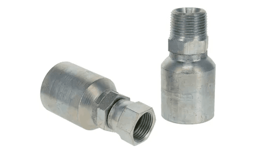
Hose size must match fittings precisely:
Key rules:
- Match dash size (e.g., -8 hose → -8 fitting)
- Verify thread type:
- NPT
- BSP
- JIC
- Ensure proper crimping or assembly
👉 Incorrect fitting selection leads to:
- Leakage
- Pressure loss
- Safety hazards
10.5 Practical Selection Example
Scenario:
- Flow rate: 70 L/min
- Pressure: 250 bar
- Application: Hydraulic cylinder
Step-by-step:
- Determine ID → ~5/8″ (-10 hose)
- Check pressure:
- Standard braided may be insufficient
- Select:
- High-pressure spiral hose (SAE R13)
- Verify:
- Bend radius fits installation
- Correct fittings (-10)
👉 Final selection:
-10 spiral hydraulic hose rated ≥ 250 bar
10.6 Common Selection Mistakes
Avoid these errors:
- Choosing hose too small → overheating, pressure drop
- Choosing hose too large → inefficient and costly
- Ignoring pressure spikes
- Overlooking environmental conditions
- Mixing incompatible standards or fittings
10.7 Key Takeaways
- Start with flow rate → determine hose ID
- Verify pressure rating and safety factor
- Consider temperature, fluid, and environment
- Ensure proper routing and installation
- Match hose with correct fittings and standards
Choosing the right hydraulic hose size is a balance of engineering calculations and real-world experience. When done correctly, it ensures your hydraulic system operates efficiently, safely, and reliably over the long term.
11. Common Mistakes When Using Hydraulic Hose Size Charts
Even experienced engineers and technicians make mistakes when using hydraulic hose size charts. These errors can lead to inefficiency, system failure, or safety risks.
One of the most common mistakes is misinterpreting dash size. Many users assume dash size refers to the outer diameter, when in fact it represents the inner diameter (ID) in 1/16 inch increments. This misunderstanding often results in selecting the wrong hose, especially when matching fittings.
Another critical issue is ignoring pressure rating. A hose may have the correct size for flow, but if it cannot withstand the system pressure, it becomes a major hazard. Always verify both working pressure and burst pressure, rather than assuming all hoses of the same size have equal strength.
Overlooking bend radius is another frequent mistake. In tight installations, hoses are often forced into sharp bends below their minimum radius. This leads to internal damage, reduced flow, and early failure—even if everything else is correctly sized.
A common problem in global projects is mixing metric and imperial systems. For example, combining a metric hose with inch-based fittings can cause leakage or installation delays. Always confirm the unit system before selection.
Finally, many users fail to consider temperature effects. High temperatures can reduce hose strength and flexibility, while low temperatures can make hoses brittle. Ignoring temperature can significantly shorten hose life.
👉 Avoiding these mistakes ensures your hydraulic system remains safe, efficient, and reliable.
12. Hydraulic Hose Size Conversion
Hydraulic hose sizing often requires converting between inch, millimeter (mm), and dash size systems, especially in international projects. Understanding these conversions is essential for accurate selection and compatibility.
Inch to mm Conversion
The basic formula is:
- 1 inch = 25.4 mm
For example:
- 1/2 inch = 12.7 mm
- 3/4 inch = 19.1 mm
Use the converter above to quickly switch between units when working with mixed standards.
Dash Size Conversion
Dash size is based on inch measurements:
- Dash size = ID (inch) × 16
Examples:
- -8 → 8/16 = 1/2 inch
- -12 → 12/16 = 3/4 inch
- -16 → 16/16 = 1 inch
This system allows quick identification of hose size without complex calculations.
Quick Reference (Common Sizes)
| Dash | Inch | mm |
|---|---|---|
| -4 | 1/4 | 6.4 |
| -6 | 3/8 | 9.5 |
| -8 | 1/2 | 12.7 |
| -12 | 3/4 | 19.1 |
| -16 | 1 | 25.4 |
Importance in Global Projects
In industries like oil & gas and EPC projects:
- US systems → inch & dash size
- European systems → metric (mm)
- Asian projects → mix of both
Incorrect conversion can lead to:
- Mismatched fittings
- Leakage
- Procurement errors
👉 Always double-check conversions and refer to manufacturer data when precision matters.
13. Applications of Hydraulic Hose Size Charts
Hydraulic hose size charts are widely used across multiple industries to ensure proper system design, installation, and maintenance. Their role is critical in any application involving fluid power transmission.
In the oil and gas industry, hose size charts are used for high-pressure systems such as drilling rigs, wellhead control systems, and chemical injection skids. Proper sizing ensures safe operation under extreme pressure and harsh environments.
In construction equipment, such as excavators and loaders, hydraulic hoses control movement and power transmission. Size charts help engineers select hoses that balance flow capacity, flexibility, and durability, especially in systems with constant motion and vibration.
In manufacturing and industrial systems, hydraulic hoses are used in presses, injection molding machines, and automation systems. Accurate sizing ensures precision, efficiency, and minimal downtime, which is critical in production environments.
The agricultural sector also relies heavily on hydraulic systems for tractors, harvesters, and irrigation equipment. Hose size charts help ensure reliable performance in outdoor conditions, where hoses are exposed to dirt, weather, and mechanical stress.
In aerospace and high-tech industries, such as semiconductor manufacturing, hose sizing must be extremely precise. Even small deviations can affect system performance, especially in cleanroom or high-purity environments.
Why Size Charts Are Essential in These Applications
- Ensure correct flow and pressure performance
- Prevent system failures and downtime
- Enable compatibility across components
- Support efficient design and maintenance
14. Maintenance and Inspection of Hydraulic Hoses
Proper maintenance and inspection of hydraulic hoses are essential to ensure system reliability, safety, and long service life. Even when hoses are correctly sized and installed, they are still subject to wear, pressure cycles, temperature changes, and environmental damage. A proactive maintenance strategy helps prevent unexpected failures and costly downtime.
14.1 Why Maintenance Matters

Hydraulic hoses operate under demanding conditions, including high pressure, vibration, and exposure to harsh environments.
Key reasons for regular maintenance:
- Prevent sudden hose failure
- Reduce downtime and repair costs
- Maintain system efficiency
- Ensure operator safety
👉 A failed hose can lead to:
- Oil leaks
- Equipment damage
- Safety hazards (high-pressure fluid injection)
14.2 Visual Inspection Checklist


Routine visual inspections are the first line of defense.
Check for:
- Cracks or cuts on the outer cover
- Abrasion or worn areas
- Bulging or blistering (sign of internal damage)
- Leaks around fittings
- Kinks or deformation
- Corrosion on fittings
👉 Any of these signs indicate the hose should be repaired or replaced immediately.
14.3 Measuring Hose Condition in the Field


Beyond visual checks, field measurements help ensure hoses are still within acceptable limits:
Key checks:
- Verify outer diameter (OD) for swelling
- Confirm bend radius is not exceeded
- Check hose routing and clamp positioning
- Ensure fittings are secure and properly aligned
👉 In critical systems, advanced methods (like pressure testing) may be used.
14.4 Replacement Guidelines


Hydraulic hoses should be replaced based on condition, not just age.
Replace immediately if:
- Visible damage (cracks, bulging, leaks)
- Exposed reinforcement wires
- Hose has exceeded pressure limits
- Repeated failures occur in the same location
Preventive replacement:
- Follow manufacturer recommended service intervals
- Replace hoses in high-risk areas proactively
👉 Always use the same or upgraded specifications when replacing hoses.
14.5 Preventive Maintenance Best Practices


To extend hose life and reduce failures:
- Use protective sleeves against abrasion
- Install proper clamps and supports
- Avoid twisting during installation
- Maintain correct bend radius
- Keep hoses away from sharp edges and heat sources
- Monitor system pressure and temperature
14.6 Maintenance Schedule (Recommended)
| Inspection Type | Frequency |
|---|---|
| Visual inspection | Daily / Weekly |
| Detailed inspection | Monthly |
| Pressure/system check | Quarterly |
| Full replacement review | Annually |
👉 Frequency depends on application severity (e.g., oil & gas vs light industry).
14.7 Key Takeaways
- Regular inspection prevents unexpected failures
- Focus on:
- Damage
- Leaks
- Deformation
- Replace hoses based on condition, not just time
- Proper installation and routing extend hose life
- Preventive maintenance reduces downtime and cost
Conclusion
Hydraulic hose sizing is far more than just selecting a diameter—it is a critical engineering decision that directly impacts system performance, safety, and long-term reliability. Throughout this guide, we’ve explored how hydraulic hose size charts serve as an essential tool for understanding key parameters such as inner diameter (ID), outer diameter (OD), dash size, pressure rating, and bend radius.
Choosing the correct hose size ensures that fluid flows efficiently with minimal pressure loss, while also preventing issues like overheating, excessive wear, and premature failure. At the same time, matching hose size with the appropriate pressure rating and construction type—whether braided, spiral, thermoplastic, or PTFE—is vital for handling real-world operating conditions.
We also highlighted the importance of reading hose size charts correctly, avoiding common mistakes, and understanding conversions between inch, metric, and dash size systems. In global industries such as oil & gas, manufacturing, and construction, these details are especially important to ensure compatibility across different standards and suppliers.
Beyond selection, proper installation, routing, and maintenance play a crucial role in maximizing hose lifespan. Even the best hose can fail if it is bent too tightly, exposed to harsh conditions without protection, or not regularly inspected.
👉 The key takeaway is simple:
The right hydraulic hose size is a balance of flow, pressure, environment, and application.
By using hydraulic hose size charts correctly and applying sound engineering practices, you can:
- Improve system efficiency
- Reduce downtime and maintenance costs
- Enhance safety in high-pressure environments
As hydraulic systems continue to evolve with higher pressures and more demanding applications, the importance of accurate hose sizing will only grow. Whether you are designing a new system or maintaining an existing one, mastering hydraulic hose size charts is a fundamental skill that delivers long-term value.

Contents1 II. The Role of Hydraulic Hoses in Hydraulic Systems1.1 1. Transmitting Hydraulic Power1.2 2. Withstanding High Pressure1.3 3. Flexibility and Movement1.4 4. Vibration Dampening1.5 5. Environmental Protection1.6 6. Easy Installation and Maintenance2 III. Construction of Hydraulic Hoses2.1 1. Inner Tube2.2 2. Reinforcement Layer2.3 3. Outer Cover2.4 Optional Features and Add-ons3 IV. Major Types of […]